Augmented Reality on Android - Drawing a Box (Part 3)
Introduction
In previous blog posts, we talked about the development process of Can It Fit?, an Augmented Reality (AR) experience available in the Edmunds Android application. In Part 1, we discussed our development approach and high level architecture. Part 2 focused on using the Sceneform library to abstract away the pain points of directly dealing with computer graphics development.
Recall that Can It Fit? is an AR experience that lets a car shopper visualize a virtual vehicle in a space and see if it fits. To do that, users draw a virtual bounding box around their real world space.
This post will focus on the implementation details of the virtual parking space. Geometrically, the virtual parking space is represented by a rectangular prism, which we’ll refer to as a “box”. We first draw the base of the box, then adjust its height with a slider. Drawing the base is performed in multiple steps by placing points on AR-detected planes within the app.
Virtual Parking Spot
To represent the box mathematically, we need eight vertices positioned in virtual 3D space and connected together to form edges and faces. Every frame of the application, the vertices update their position according to user input. We look at the box as a single object and its vertices and faces as internal data or properties. We also know that the box needs to be able to reposition, rotate, and scale. Understanding the underlying data and desired behavior, we can sketch a rough model of a Box class.
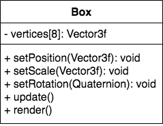
Drawing the box on the screen is another “dimension” to the problem. Since the most common OpenGL ES primitive for drawing objects is a triangle (Part 2), we would need to break every face of the box into triangles (two at a minimum, because one rectangle can be broken into two triangles), and send its vertex information to the GPU using OpenGL ES API calls. Vertex sort order also matters, which adds another level of complexity for us to maintain in the codebase. Ideally, we would like to have an object that takes care of the box internal implementation and rendering details, and exposes methods that are meaningful to update logic such as changing the center and length of the sides.
Once we made the switch to Sceneform, we took advantage of the makeCube method from the ShapeFactory class. The method takes center, size, and material (in our case, a color with transparency) parameters and provides us with a ModelRenderable object that we can update, which is exactly what we wanted. Under the hood, Sceneform takes care of all the vertex updates and graphics API calls.
User Flow
Now that we have discussed the implementation concerns, let’s take a look at the user flow. The user is tasked with placing and orienting the box in virtual world by setting corners and adjusting dimensions. Below is the flow for completing the box:
- Place the first corner (pt1). This will be one of lower vertices on the box.
- Trace a horizontal line from pt1 and place a second corner (pt2), connecting with pt1. Now we have an edge, a line between two lower corners (vertices).
- Once we have an edge, knowing that shape of the base of our box is rectangular, we can stretch it in a direction that is perpendicular to the edge to give it depth. That completes the rectangular base.
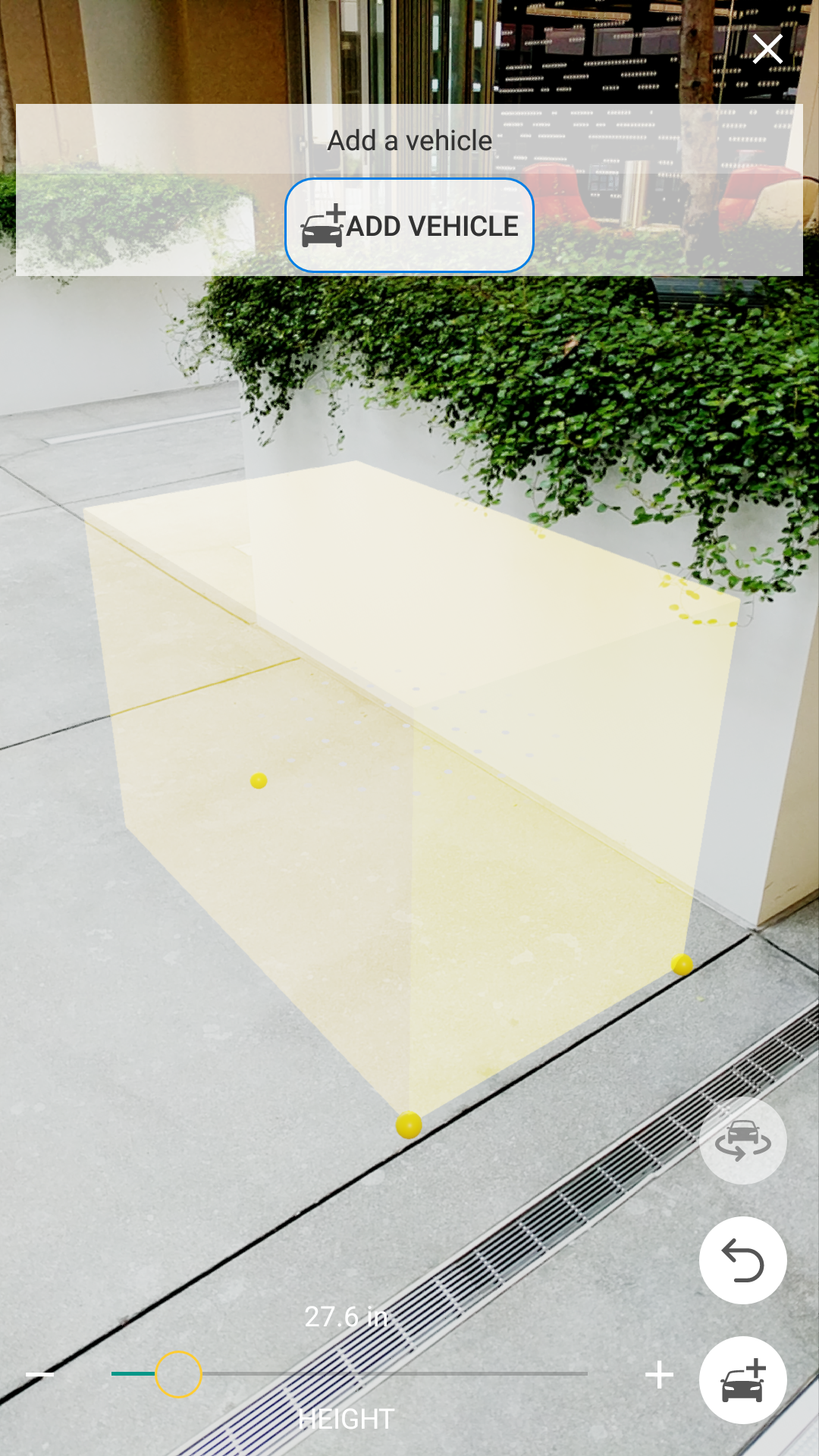
- Set the height to extend the rectangular base vertically and complete the box.
Implementation Details
Now that we’ve established the user flow and geometric requirements for drawing the box, we need to determine an implementation. There are multiple ways this can be done.
The approach we took is to create a unit box at the start of the application, where all its sides are length of one. During each frame draw, the box’s scale, position, and orientation is updated based on the user’s input and the application state transition. We can hide the box in the early application states by scaling all of the sides to zero, shaping it into a rectangle by setting the height to zero, or stretching it to look like a line. As the user progresses through experience, the box is updated until it is complete.
We took advantage of the Sceneform library and made our Box extend the Node class. A Node represents an object in scene graph that renders a given mesh (box mesh, in this case) and is updated every frame by overriding the onUpdate() method, where we add our application logic to update world position, orientation, and scale.
Now we’ll look at how we handle different cases in the onUpdate() method.
Case 0
Given: tracker.
Task: place the first point pt1 on the horizontal floor plane. It will represent one of the vertices of the box.
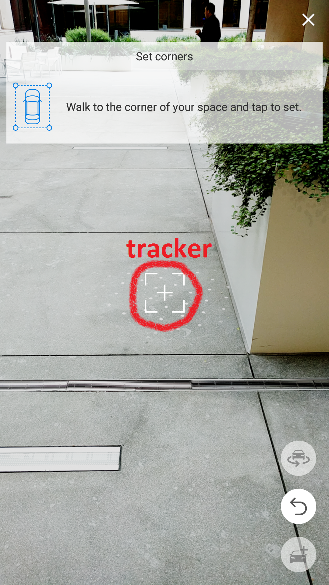
We call this “Case 0”, because we don’t have any points placed (anchored in virtual world) yet. This is our starting position and the only thing that is available is what we call a tracker - the center of the screen ray traced to a virtual plane. It represents a point in the virtual world where the center of the camera is aimed.
Since the only “point” we have is the tracker in this state, we set the center of the box to its position and scale the sides of the box to zero to make it invisible.
When the user taps on the screen, a first point is placed (anchored) at the intersection of the ray and the first virtual plane it hits, which we expect to be the floor plane, but any other horizontal plane will work the same.
Case 1
Given: tracker, pt1
Task: place second point pt2 on the same horizontal plane as pt1. Second point will represent another vertex of the base of the box. A line connecting the two points will be an edge of the box.
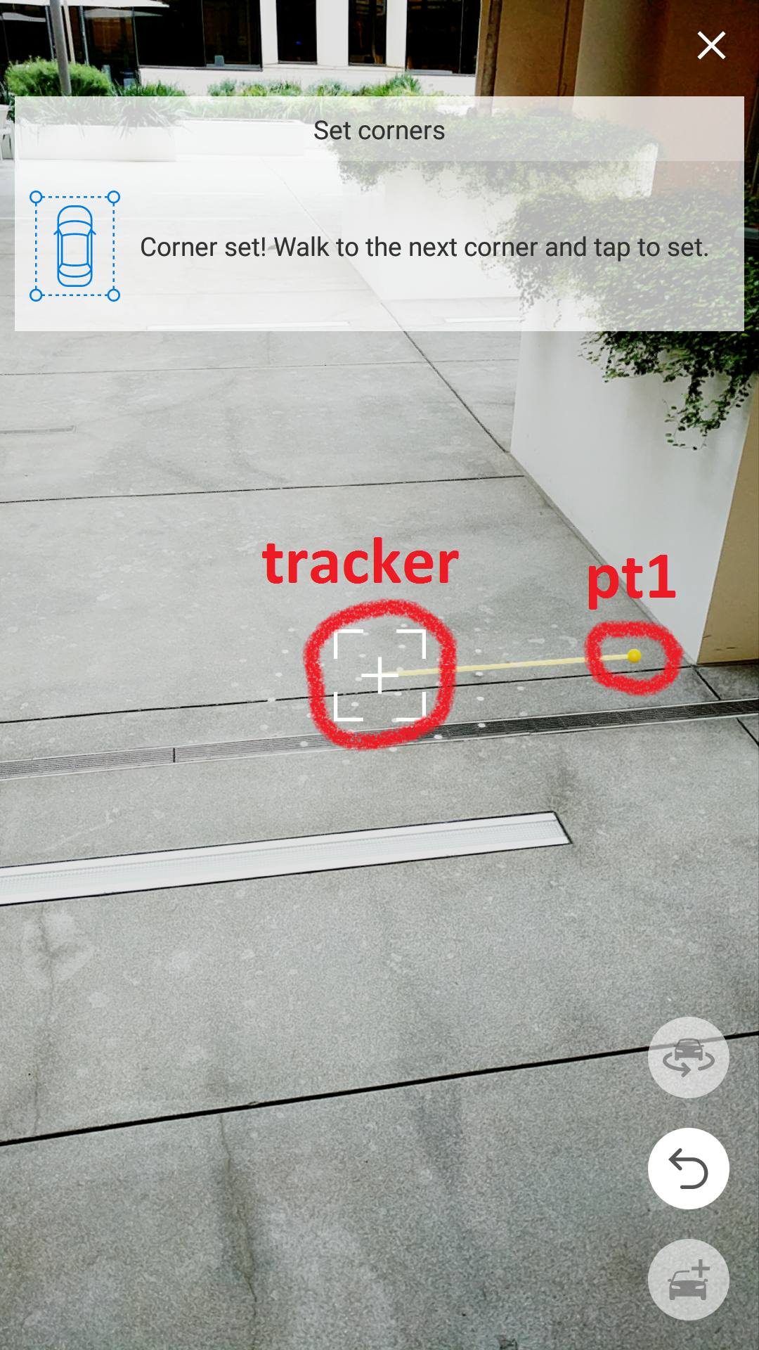
Now that we have pt1 anchored to a virtual location in the world, the logic for updating the box in this state will be different. When moving the camera around, we want a line to be drawn from previously placed pt1 to the tracker. The line is a visual indicator of the side of the box. The line is actually a box object with one dimension scaled to the length between pt1 and the tracker with the box center being the midpoint and infinitesimal height and width to make it a line. To accomplish this, we need to apply some updates to our Box class.
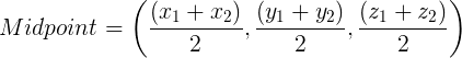
For the center, we need to find the midpoint of pt1 and tracker. The ARCore framework allows us to access x, y, and z coordinates of those points. Now, we just apply midpoint formula and we have the center of the box.
Then one of the sides is chosen to be of length that is the distance between pt1 and tracker, and other sides are scaled to a number close to zero so that it looks as thin as a line on a phone screen.

Case 2
Given: tracker, pt1, pt2
Task: While pt1 and pt2 form an edge of the base of the box that we may label width, move the tracker into the distance and place a point pt3 to mark how far you want the length of the box to extend.
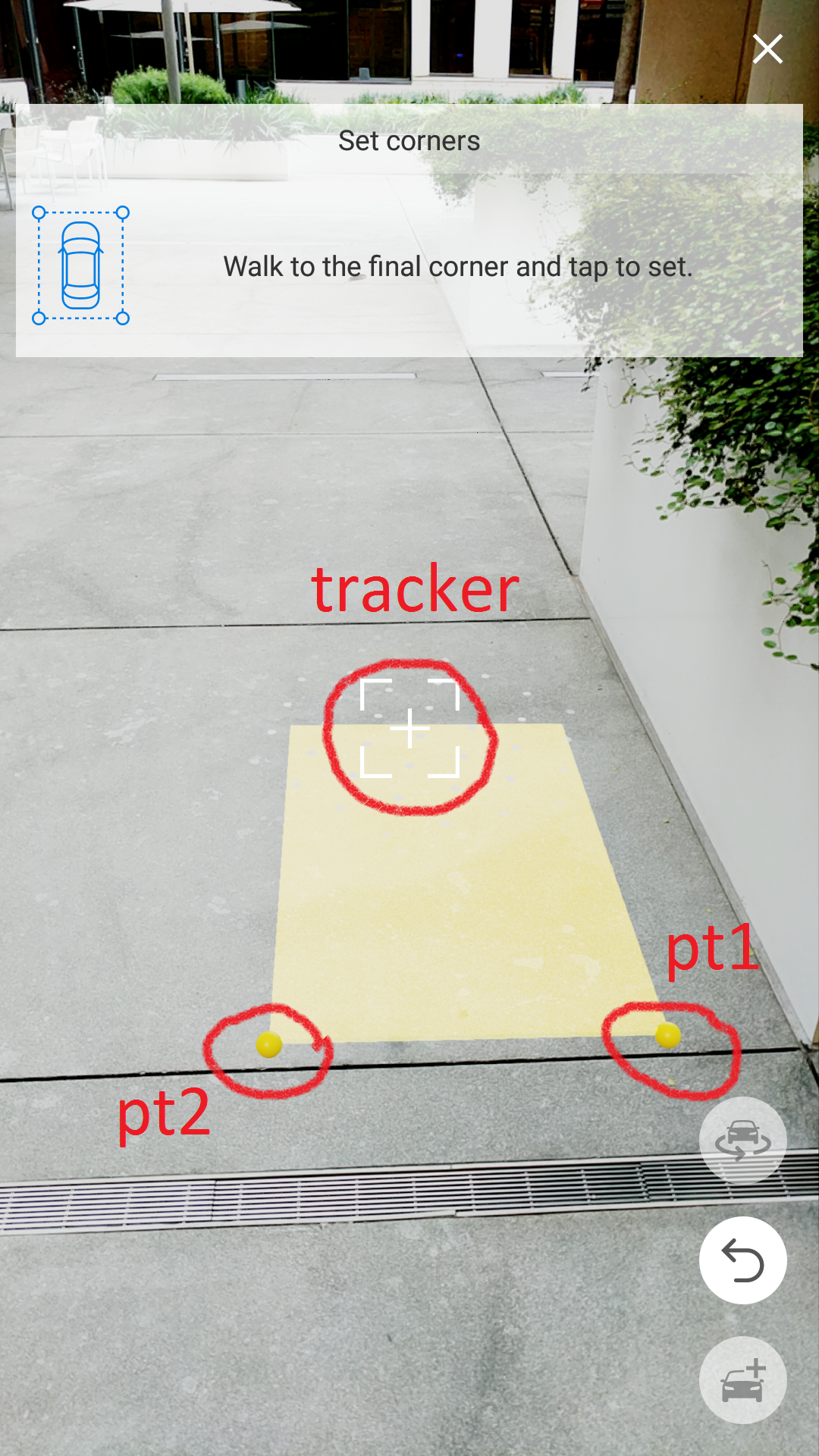
This is the most interesting case, in my opinion. Since we are still working with the base of the box (height is still set to a very small number that it looks flat), we can visualize this problem in 2D for simplicity.
As the tracker goes off into the distance away from the edge between pt1 and pt2, the perpendicular it casts onto the extended edge line will be the length of the base (assuming the first dimension we call the width). And the new box center will be the midpoint between pt1 and pt2 offset by half the distance of the perpendicular.
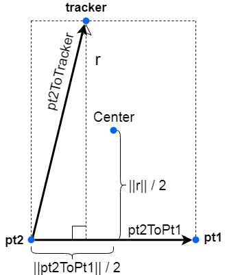
There are multiple computational paths we can take to get us what we are looking for. The simplest one is to to use a rejection formula to find the rejection r of vector pt2ToTracker on vector pt2ToPt1. Rejection r is a vector orthogonal to pt2ToPt1. Computing its length gives us length of the box. To find the center of the rectangular base, we offset the midpoint between pt1 and pt2 by half the length of r in the direction of r.
Once the user taps on the screen to anchor the tracker onto pt3, the base of the box is set. From now on, the base of the box is anchored in place and the only variable left to set is the height. It can be adjusted using the slider on the bottom of the screen.
Orientation
So far all the transformations we’ve discussed deal with positioning the center of the box and scaling its sides. Another very important transformation that must be updated every frame is the orientation of the box relative to the forward direction of the world. Without properly orienting the box, we can’t expect its positioning and scale will give us the desired result.
When ARCore is initialized, it creates a world coordinate frame. The world forward vector points roughly in the same direction where the phone is facing during initialization with the world up vector pointing vertically upward. Any world transformations that are done on objects in the scene are in relation to the world coordinate frame.
When an object is first created, it doesn’t have a rotation value and gets placed with its default orientation, which is the same direction as world’s forward vector. This wasn’t acceptable to us, because we can’t expect the user to perfectly align the orientation of the box in the direction they want.
Before we can find the offset from the world forward, we must first find the new forward vector of the box. We do so by computing cross product between vector that goes from pt1 to pt2 and the up vector. This results in a vector that is both orthogonal to the edge between pt1 and pt2 as well as the vertical up vector. Note that our up direction of the box does not change and stays the same as the up direction of the world. All rotations are done around the world y-axis (in OpenGL, y-axis points upward). We are never “tilting” the box, because it is positioned on a horizontal plane (ARCore is limited to horizontal plane detection as of development of the project). Once we obtain the new forward direction, we can use it to compute the new orientation value.
Lessons Learned
To conclude, I’d like to share some things I learned along the way that enhanced my effectiveness while working on computer graphics applications.
- Think of vectors, instead of offsets. Where direction matters, it is helpful to get in the mindset of thinking in terms of vectors. For example, if we have two points A and B, it may be useful to think of the translation from one to another using vector operations such as addition and/or subtraction, instead of just a scalar offset.
- Draw diagrams on paper. When working out transformations of points or objects, it helps to draw the problem on paper so the whole picture can be seen clearly. Typically, I draw the coordinate frame (reduce the problem to 2D for easier visualization on paper, if possible), the starting position, and the desired position of where I want the point or object to end up. Then, I gather all the knowns and start applying mathematical operations to get to the result I’m looking for. Sometimes having a visual picture of the problem is very helpful when coding it out.
- Do mathematical computations on paper. It is tempting to perform small mathematical computations in your head. The problem with that becomes clear when you realize there are so many of those computations, that you easily lose track of them. I find it helpful to perform even very small and easy computations on paper, so that I can quickly reference back to the result. This reduces amount of errors I make and frees me from needing to memorize intermediate results.
- Keep track of degrees vs radians. Both degrees and radians are angle units of measure. They may be used in trigonometric functions, rotation, angle offsets, coordinate systems. A programmer should always be aware of which units are used where. Using wrong units may not raise an error, but instead result in unexpected behavior. If you are using libraries, make sure you know which units are expected as input. Some libraries use degrees while others use radians, and sometimes they use both. Have a quick and reliable way of converting from degrees to radians and vice versa. Consider naming your variables in a way that reflects units used (example: rotationDegrees, offsetRadians).
- If you are stuck on a problem for a while, step away and take a break. There are times when I get stuck on a problem and stop making progress. It becomes pointless to stare at the lines of code and not progress toward a solution. I discovered that the best thing to do is to allow myself to take a break and disengage from the problem. Just step away. Make some coffee, look out the window, or pick up a musical instrument. In other words, engage in a task that feels like a mental break from what you are stuck on. In my experience, taking a breather allows for some inspiration to solve the problem at hand.
Links
- Developing Augmented Reality Application For Android (Part 1)
- Using Sceneform to Develop Can It Fit? For Android (Part 2)
- Augmented Reality on Android - Drawing a Box (Part 3) - This article
 Denys Vorontsov is a Senior Software Engineer at Edmunds.com